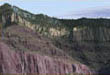
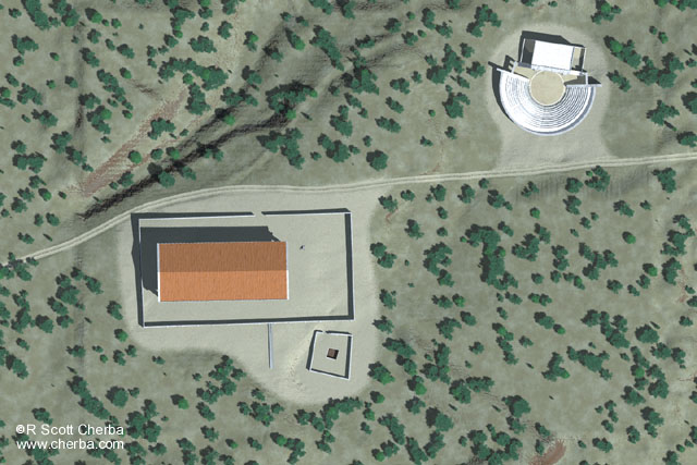
 Figure 1. Plan view. View width is approximately 300 m. 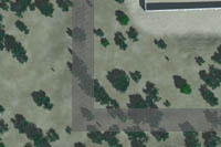 Figure 2. Figure 1 detail of southwest corner 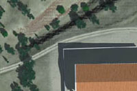 Figure 3. Road north of temple 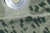 Figure 4. Road south of theater 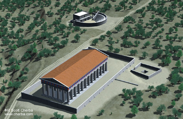 Figure 5. View northeast 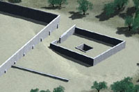 Figure 6. Terrace wall ( lower left) and pit 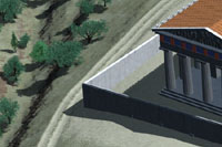 Figure 7. Temenos wall, northwest corner 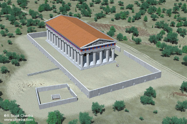 Figure 8. View northwest 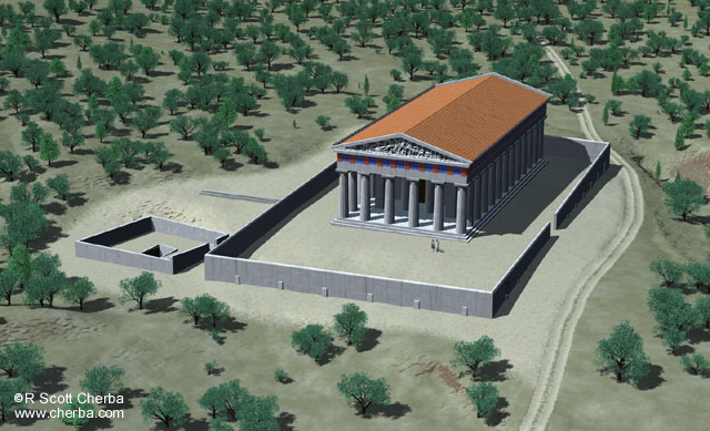 Figure 9. View southwest 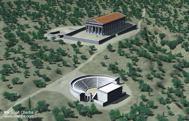 Figure 10. View southwest 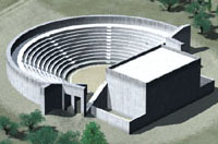 Figure 11. Theater |
Sanctuary Production Notes These reconstructions are based on work originally performed for Archaeological Graphic Services. As is usually the case, budget was limited in the original project and several data problems went unresolved. I overhauled the project, corrected data problems as best I could, and created a scene suggestive of what a sanctuary might look like through my eyes. This was an independent project and the scenes reflect my research, interpretation of the data, and artistic vision. Any resemblance between these scenes and an actual site that may have existed in the past is purely coincidental ;). Terrain The terrain in the immediate area of the temple and theater is based on one dataset and the surrounding area is based on another. Unfortunately, they don't match where the datasets meet. Data errors were hidden in original renders by dense foliage and judicious camera placement. These errors were quite obvious in most views when foliage density was reduced and plan views generated. Terrain was modified where the imported datasets met to make the discrepancy less noticeable. Attempts were made to change the terrain as little as possible while creating the illusion of topographical continuity. The transition is faintly visible as a rectangle within the bounds of the plan view (Figure 1). Figure 2 is a detail from the southwest corner with the transition zone shaded. While the terrain is no longer true to the imported datasets, the datasets themselves lack agreement. In other words, the terrain doesn't look like the data says it should, but it looks more like terrain should ;). Other changes made to the terrain were a direct result of the road. The original terrain datasets, reconstructed for the time period, were not detailed enough to show the road. As a result, the terrain did not reflect the impact of road construction and use. Significant cut and fill work was performed to create a realistic road bed, most notably north of the temple (Figure 3) and south of the theater (Figure 4). This impacted the terrain on both sides of the road. Again, these changes to the terrain reflect a deviation from the original datasets. Architecture With the exception of the theater, original architecture was modeled to fit one of the original datasets. As would be expected, changes to the terrain required changes to the models to make them fit the new topography. The terrace wall (Figure 6) was moved several meters west. In its original position it hung over the slope west of the pit wall. While this may be the least accurate solution, it was easier to move the wall than reshape the terrain to conform to it. The pit (Figure 6) was lowered to match the terrain and the pit wall was corrected for the terrain it rested on. The temenos wall around the temple was also corrected to fit the terrain, most notably at the southeast and northwest corners (Figures 6 and 7, respectively) The temple itself required the most work, although the majority of it was 3D model repair. The original model was produced in 3D Studio MAX by Dale Mertes (Digital Media Lab, University of Chicago). The model was revised and roof tiles added in AutoCAD by Peggy Sanders. By the time I received the model, cumulative DXF errors required substantial polygon work in LightWave to make the model usable. The resulting model, while different at the polygon level, looks similar to Sander's original DXF at the scale of these images. A major change to the original temple design is my addition of pediment sculpture. While there is no evidence for pediment statuary, it was a common temple decoration. The sculpture illustrated is a bump map texture from the west pediment of the Parthenon¹ ². (At least Poseidon is in it :). It gives the illusion of detail at a distance. The theater northeast of the temple (Figure 11) was modeled in LightWave in the site footprint of the actual theater, but the architecture is entirely conjectural. It is based on the theater at the Sanctuary of Epidaurus, built about the same time (4th c. BC) and designed by Polykleitos the Younger. Foliage The forest mix is based on my observations and photographs around Acrocorinth and along the Gulf of Corinth. All trees are 3D models built in Onyx Tree Pro. 3D models were used in place of tree images to allow control over texture, lighting, and shadows, and to create realistic trees in plan views. Olive (Olea
europaea)
Turkey oak
(Quercus cerris)
Laurel (Laurus
nobilis)
|
|||||||||||||||||||||||||||||||||||||||||||||||||||||||||||||||||||||||||||||||||